1,Introduction-Understanding the Complete Corrugator and Converting Lifecycle
For modern packaging plant investors, plant managers, and procurement officers, mastering the corrugated box manufacturing process is the single most critical step to achieving a high-efficiency, zero-waste factory floor. Many newcomers to the paper packaging industry view box making as a simple cutting and folding operation. In reality, it is a highly calibrated, two-stage industrial heavy-manufacturing lifecycle.
The process is strictly split into two major zones on your shop floor:
- The Corrugating Stage (The Wet End and Dry End): Where raw, flat rolls of kraft paper are unreeled, heated, chemically combined with starch, fluted into structural waves, and glued into rigid 3-ply, 5-ply, or 7-ply sheets on a massive corrugated line machine.
- The Converting and Packaging Stage (The Post-Processing): Where those rigid, flat sheets are fed into a high-speed corrugated box printing machine, sliced, creased, slotted, folded, glued, and finally stacked onto transport pallets by an automatic palletizing robot for shipment.
If any single machine in this interconnected chain fails to maintain synchronization, your entire factory floor grinds to a dead stop. This comprehensive, 3000-word masterguide will take you step-by-step through every critical machine center, highlighting the mechanical secrets that separate low-end, high-waste operations from world-class, automated packaging plants.

Phase 1 (The Wet End)-Unreeling and High-Speed Web Feeding
The life of a corrugated box begins at the "Wet End" of the corrugator line. This is where massive rolls of raw containerboard, weighing up to 4 tons each, are converted into continuous moving webs of paper. The stability of this initial feeding phase dictates the flat alignment and structural strength of the final board.
The Foundation: The Shaftless Hydraulic Mill Roll Stand
Before any corrugation can happen, the heavy paper rolls must be hoisted into the air and held perfectly dead-center. This task is executed by the heavy-duty hydraulic mill roll stand.
Modern, premium stands are completely shaftless. Instead of operators manual sliding a heavy steel rod through the paper core, the roll stand utilizes dual-axis hydraulic arms that open, close, lower to floor level, and lift the roll automatically.
To prevent web drifting, the stand maintains a steady lateral alignment while pneumatic multi-point disc brakes apply continuous back-tension. This tension prevents the paper from sagging or wrinkling as it rushes into the machinery at speeds exceeding 250 meters per minute.
[Raw Roll on Floor] ──► [Hydraulic Arms Clamp Core] ──► [Pneumatic Disc Brakes Set Tension] ──► [Smooth Web Exit]
Zero-Downtime Continuity: The Automatic Paper Splicer
A standard paper roll runs out every 20 to 30 minutes at high production speeds. Stopping the entire corrugator line to thread a new roll of paper would destroy your factory's efficiency and warp the paper inside the heated glue stations. To achieve non-stop production, plants install an automatic paper splicer directly above or behind the mill roll stand.
The automatic splicer acts as a high-speed mechanical bridge. While the active paper roll is spinning into the machine, the operator prepares the "tail" of a fresh backup roll on a splicing matrix using heavy-duty double-sided adhesive tape.
The moment the active roll hits its pre-calculated inner core limit, a laser sensor triggers the splicer. A flying indexing knife cuts the dying web while a high-pressure indexing roller instantly stamps the moving tail of the old web onto the adhesive tape of the new roll. This seamless splice happens in less than 1 second without dropping line speed, ensuring a continuous ribbon of paper flows into the heating zones.
Read More : 《How To Calculate Hydraulic Mill Roll Stand ROI》
Read More : 《Fine-Tuning Splicer Tension Dynamics To Prevent Web Tears》
Phase 2 (The Fluting Core)-The Single Facer and the Creation of the Fluted Wave
Once the flat paper webs are feeding smoothly, they pass into the heart of the wet end: The Single Facer. This is the machine center where flat paper is given its iconic structural strength through the creation of the "flute" (the wavy middle layer of a cardboard sheet).
Flute Medium (Flat Paper) ──► [Steam Heat & Moisture] ──► [Corrugating Rollers] ──► [Wavy Corrugated Flute Wave]
The transformation relies on three distinct physical actions inside the Single Facer:
Steam Pre-Conditioning: The flat paper web chosen to be the flute medium is exposed to intense steam heat and moisture inside a drum pre-heater. This moisture softens the cellulose fibers in the paper, making the web highly pliable and stretchable without tearing.
The Corrugating Rolls: The conditioned paper is immediately pulled between two giant, interlocking steel cylinders known as corrugating rolls. These rolls feature precisely machined wave profiles (such as A, B, C, or E flutes) that mesh together under intense hydraulic pressure. As the paper passes through, it is forced to take on the permanent wave shape of the steel teeth.
Glue Application and Liner Bonding: While the fluted wave is held in place by vacuum suction or mechanical fingers on the corrugating roll, a precision glue applicator roll applies a micro-layer of starch-based adhesive to the top tips of the waves. Concurrently, a flat "liner" paper web is pressed against these glued tips under the force of a heavy pressure roll. The intense heat instantly gelatinizes the starch glue, creating a permanent, rigid bond. This creates a "single-face" web (one flat liner sheet glued to one wavy flute sheet).
Read More:《What Is A Single Facer Corrugated Machine?》

Phase 3 (The Dry End)-Combining, Heating, and Double-Facer Bonding
To make a standard 3-layer (single-wall) or 5-layer (double-wall) board, the single-face web created in Phase 2 must travel up a bridge conveyor to the Double Facer (or Hot Plate Section). This zone represents the beginning of the "Dry End" of the corrugated line machine.
Here, multiple single-face webs are layered together. Another glue machine applies starch adhesive to the exposed bottom tips of the flutes. Finally, a bottom flat liner paper is introduced to seal the sandwich shut.
The combined layers then enter the Drying and Baking Tunnel. This section consists of a long series of solid, steam-heated cast-iron hot plates beneath a heavy, continuous top traction belt. As the combined board slides over the hot plates at high speed, the intense heat completely dries the wet starch adhesive, turning it into a crystalline, rock-solid chemical bond.
This baking process cures the cardboard, giving it the vertical top-to-bottom compression resistance required to prevent finished boxes from crushing when stacked inside shipping containers.
Read More:《What Is A Double Facer?》
Read More:《What Are The Differences Between Single Facer And Double Facer Machines?》

Phase 4 (The Slitting and Scoring Stage)-Precision Slitter-Scorers and Cut-Off Knives
At the exit of the drying tunnel, the cardboard is now a continuous, rigid, wide ribbon of multi-layer board. The final step of the corrugator machine lifecycle is to slice this massive web into individual, flat sheet dimensions ordered by your clients. This is executed by two highly automated dry-end machine centers:
- The Computerized Slitter-Scorer: This machine utilizes independent, thin-profile tungsten carbide blades and creasing wheels mounted on a motorized traveling gantry. Controlled by the factory's central scheduling software, the slitter-scorer automatically shifts its blades laterally in millisecond windows to trim the rough edges of the moving board, slit the wide web into multiple narrow widths, and stamp sharp crease lines (scores) down the length of the board. These crease lines are critical because they define where the final box flaps will fold.
- The High-Speed Cut-Off Knife: Immediately following the slitting process, the narrow strips of creased board enter the cut-off knife. This machine features dual counter-rotating steel drums equipped with heavy, helical cutting blades. Driven by high-torque servo motors, the drums rotate in perfect synchronization with the line speed to chop the moving board crosswise into exact sheet lengths. The cut sheets are then transferred onto a shingling conveyor and sent to a downstacker, ready to be moved to the converting department.
Read More:《What Is A Thin-blade Slitter Scorer Machine?》
Read More:《Top 10 Thin Blade Slitter Scorer Machine Manufacturers in China 2026》

Wet-End and Dry-End Technical Specification Matrix
To guide your engineering teams when purchasing or auditing the front end of your box production line, utilize this direct hardware baseline matrix:
Table 1: Core Technical Baselines for Wet and Dry End Machinery
| Machine Center | Critical Hardware Baseline | Direct Impact on Product Quality |
| Mill Roll Stand | Solid welded steel base (>2.8 tons) Dual-way automatic hydraulic locks |
Eliminates high-speed vibration & edge cracks. Prevents safety drops during hose bursts. |
| Automatic Splicer | High-pressure rolling matrix Dual brake tension control pads |
Guarantees 99.9% splice success rate on thin paper. Prevents web sagging during roll changes. |
| Single Facer | Tungsten carbide corrugating rolls Integrated vacuum suction box |
Maintains precise flute height over 50 million meters. Holds flute wave perfectly stable at 250+ m/min. |
| Double Facer Hot Plates | Steam pressure regulation up to 16bar Heavy-duty top traction blanket |
Guarantees deep starch crystallization for flat boards. Provides uniform downward pressure without crushing flutes. |
Phase 5 (The Converting Stage)-High-Speed Flexographic Printing and Slotting
Once the downstacker at the end of the corrugator discharges flat, rigid cardboard sheets, the raw board manufacturing phase is complete. The material now enters the Converting Department. This is the section of the factory floor where a plain sheet of brown board is transformed into an identifiable, brand-specific shipping container.
The primary engine behind this transformation is the high-speed corrugated box printing machine. Modern converting operations utilize a specialized inline setup known as a Flexo Folder Gluer (FFG) or a standalone Flexo Rotary Die Cutter. This massive machine center processes thousands of sheets per hour through several inline sub-stations:
Raw Flat Sheets ──► [Flexo Print Stations] ──► [Slotting Unit] ──► [Rotary Die Cutter] ──► To Folder Gluer
- The Lead-Edge Feeding Station: Flat sheets are pulled from a heavy stack one by one using a high-vacuum suction belt system. It is critical that the feeding gate remains perfectly parallel; if a sheet enters at a slight angle, the entire downstream printing and cutting registration will be ruined.
- The Flexographic Printing Stations: The board traveling at high speed passes beneath a series of printing stations. Each station represents a single ink color (Cyan, Magenta, Yellow, Black, or custom brand Pantone shades). A rubber or photopolymer printing plate wrapped around a rotating cylinder receives a micro-layer of water-based ink from a laser-engraved ceramic Anilox roller. The plate then transfers the ink directly onto the cardboard with light pressure. Premium machines utilize vacuum-transfer architectures to hold the sheets perfectly flat, preventing color misregistration or smudging.
- The Slotting Unit: After receiving its graphics, the printed board rushes into the slotting module. Here, pairs of rotating steel knives punch out deep notches along the front and back edges of the sheet. These notches create the four independent flaps of a standard shipping box. Concurrently, scoring wheels stamp deep transverse creases that define the vertical corner folds of the box body.
- The Rotary Die Cutter: For complex box designs that require custom hand-holes, ventilation ports, geometric angles, or display windows, the sheet passes through a rotary die cutting station. A curved wooden die board embedded with razor-sharp steel cutting blades and rubber ejection pads presses against a hard polyurethane anvil cylinder, stamping out custom shapes in milliseconds.
Read More:《The Guide Of The Flexo Folder Gluer (FFG)》
Read More:《Flexo Folder Gluer (FFG) Trends 2026》

Phase 6 (Final Assembly)-Folding, Gluing, and Squaring the Box Shop Floor
Now that the sheet is printed, notched, and creased, it resembles a flat, unfolded cross profile. To become a functional container, the flat sheet must be folded into a 3D tube and sealed along its structural joint. This occurs within the Folder-Gluer Module.
- The Glue Application Node: As the flat sheet exits the slotting unit, a high-speed electronic extrusion glue gun shoots a precise line of cold, fast-tacking PVA adhesive along the narrow "glue tab" on the outer margin of the board. Optical sensors verify that the glue line is consistent; a missing drop means the box will split open on the customer's assembly line, while an over-spray will glue multiple finished boxes together inside the bundle.
- The Folding Belts: The board is carried forward by a pair of twisted, high-friction folding belts. These belts slowly flip the two outer panels of the cardboard sheet inward by exactly 180°, folding them tightly along the vertical score lines stamped by the slotting unit.
- The Squaring and Counter-Ejecting Station: Folding a stiff piece of corrugated board at 300 sheets per minute can introduce geometric errors known as "fishtailing," where the edges of the box do not align perfectly square. To correct this, the folded boxes enter a squaring section equipped with vibrating side paddles that tap the box into a perfect 90° rectangle. The squared tubes are then pushed into a counter-ejector, which counts the boxes and stacks them into tight bundles of 10, 25, or 50 pieces.

Phase 7 (The Final Step)-End-of-Line Automation via the Automatic Palletizing Robot
At this stage, the manufacturing and converting processes are entirely complete. You have tight, counted bundles of finished boxes flying out of the counter-ejector every few seconds. However, if your plant still relies on manual human labor to lift, turn, stack, and palletize these heavy bundles onto wooden shipping skids, your entire high-speed corrugated line machine setup faces an immediate end-of-line bottleneck.
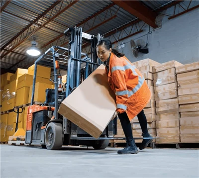
Manual stacking cannot keep pace with a converting line running at 300 boxes per minute. Human workers suffer from physical fatigue, back strain injuries, and inconsistent stacking patterns that cause pallets to tip over during warehouse transit. To eliminate this operational bottleneck, high-efficiency plants anchor an automatic palletizing robot at the absolute end of the production cycle.
Bundles from Ejector ──► [Motorized Conveyor] ──► [Robot Gripper Picks Bundle] ──► [Precise Layer Stacking]
The automatic palletizing robot acts as the final automated coordinator on your shop floor:
- Smart Bundle Infeed and Pattern Orientation: The counter-ejector discharges bundles onto a motorized roller conveyor. As the bundles approach the robotic work cell, sensors read their dimensions. The robotic controller calculates the most space-efficient stacking pattern (interlocking block configurations) to maximize pallet stability.
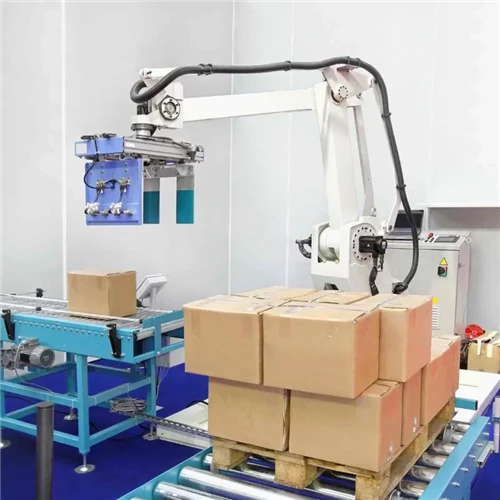
- The Specialized Robotic End-of-Arm Tooling (EOAT): The heavy-duty robotic arm, typically a 4-axis or 6-axis articulated industrial manipulator, swings into position. It utilizes a highly specialized mechanical fork gripper, side-clamping plates, or a high-volume vacuum sponge pad to smoothly lift one or multiple box bundles simultaneously without crushing the fragile corrugated edges.
- High-Speed Precision Stacking: The robot effortlessly transfers the bundles onto an empty wooden pallet, positioning them down to the millimeter according to the pre-programmed pattern. It alternates the orientation of each layer to "tie" the pallet together, ensuring the load remains perfectly stable. Once a pallet reaches its maximum height, the robot automatically signals the pallet-discharge conveyor to send the load to an automatic stretch-wrapper, while an automated pallet dispenser feeds a fresh, empty skid into the work zone.
Read More:《Palletizers Vs. Manual Labor:Choosing The Right Solution For Your Business Storage Pallet Racking》

Complete Plant Converting and Stacking Specification Matrix
To guide your engineering teams when purchasing or auditing the post-processing and packaging sections of your box production line, utilize this direct hardware baseline matrix:
Table 2: Core Technical Baselines for Converting and Palletizing Machinery
| Machine Center | Critical Hardware Baseline | Direct Impact on Product Quality |
| Flexo Printer | Vacuum sheet-transfer system Ceramic Anilox rolls (laser etched) |
Ensures perfect color registration without smudging. Delivers uniform ink density for high-definition graphics. |
| Slotting & Die Cutting | Motorized computerized axis tuning Anvil trimming oscillation mechanism |
Allows order changeovers in under 2 minutes. Extends polyurethane anvil life for clean die cuts. |
| Folder Gluer | Vibrating side squaring paddles Non-contact electronic glue gun |
Eliminates fishtailing; ensures perfectly square boxes. Prevents messy adhesive overflow and dry joints. |
| Palletizing Robot | Multi-axis heavy industrial arm Modular fork/clamp utility gripper |
Eliminates labor bottlenecks; runs 24/7 non-stop. Prevents compression damage to finished box flaps. |
Need help choosing the right corrugated box manufacturing machinery for you? Contact our team for a free consultation based on your paper size and production volume requirements.