1. Classification of Package Dimensional Variance and Mechanical Risks
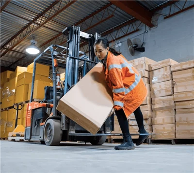
In automated secondary packaging and end-of-line logistics, incoming material irregularities represent a primary source of operational disruption. Packages rarely conform perfectly to nominal CAD dimensions due to manufacturing tolerances, ambient moisture variations, and internal product shifting. Handling these deviations requires specialized equipment configurations.
1.1 Specific Material and Defect Classifications
Warped Cardboard and Corrugated Boxes
- Physical Cause: Ambient humidity fluctuations cause differential moisture absorption between the inner and outer liners of corrugated board, leading to structural sheet warp.
- Mechanical Consequence: A warped box top surface creates a non-planar contact zone, which prevents vacuum suction cups from forming a hermetic seal, resulting in pickup failures or mid-travel package drops.
Over-Filled Bags and Bulging Cartons
- Physical Cause: Volumetric over-expansion occurs when internal product settling or gas entrapment forces the flat vertical walls of a container to assume a convex shape.
- Mechanical Consequence: Bulging packages shift the calculated center of gravity and alter the physical footprint, which causes side-clamping grippers to exert uneven pressure, resulting in stack misalignment.
Linear Dimensional Deviations
- Physical Cause: Cumulative cutting, scoring, and folding tolerances during upstream box manufacturing create variations in the absolute length, width, and height of finished packaging units.
- Mechanical Consequence: Standard fixed-coordinate pick-and-place programs fail to compensate for structural size changes, leading to physical collisions or accumulation gaps on the pallet layer.
Uneven Product Weight Distribution
- Physical Cause: Asymmetric internal product placement or fluid shifting within liquid containers creates internal mass imbalances.
- Mechanical Consequence: During high-speed angular rotation by the robotic arm, uneven mass generates unexpected rotational moments (M = F * d) that exceed the pre-set torque limits of the servo motors.
1.2 Quantitative Analysis of Packaging Defects and System Impact
| Defect Designation | Measurable Dimensional Tolerance Range | Primary Mechanical Point of Failure | Direct Impact on Stacking Stability |
| Surface Warpage / Concavity | > 5mm deviation from true horizontal plane over a 300 mm span. | Vacuum cup seal failure due to air bypass at the cup perimeter. | High risk of dropped packages; incomplete pallet layers due to missing units. |
| Side Wall Bulging / Convexity | +8mm to +15mm expansion beyond nominal width specifications. | Mechanical gripper slip or localized crushing of the package structure. | Unstable column stacking; irregular layer dimensions exceeding standard pallet boundaries. |
| Linear Length / Width Variance | ±3mm to ±6mm variance from nominal box blueprints. | Inaccurate center-point calculation by fixed-position end-effectors. | Accumulation of spacing errors across layers, causing rows to overhang the pallet edge. |
| Volumetric Height Variance | ±4mm to +8mm deviation from nominal vertical height. | Premature physical contact or mechanical crash of the robot Z-axis tool face. | Interlocking layers fail to remain level, leading to an inclined, unstable stack. |
Read More: 《How To Reduce Downtime in Your Corrugated Box Plant: A Practical Guide》
2. Upstream Mechanical Centering and Squaring Systems
Before an automated material handling cell attempts to grip a package, the incoming unit must be mechanically conditioned to minimize geometric variance. Relying solely on the robotic arm to correct physical misalignments reduces cycle efficiency. Integrated upstream mechanical correction systems ensure repeatable picking coordinates.
2.1 Technical Specifications of Mechanical Correction Units
Pneumatic Side Squaring Plates
- Operational Mechanism: Dual opposing plates driven by double-acting pneumatic cylinders compress the incoming package along its width axis before it enters the pick zone.
- Engineering Function: This system compresses slightly bulging sidewalls and forces warped box corners back into a true rectangular orientation (90° angles), resetting the structural baseline.
V-Groove Centering Roller Conveyors
- Operational Mechanism: Interlocking, angled rollers driven by a common line shaft physically guide incoming packages toward the absolute longitudinal centerline of the conveyor path.
- Engineering Function: It eliminates lateral position variance (Y-axis drift) caused by upstream merging lanes, ensuring the package center point aligns with the robot's taught pickup coordinate.
Proportional Pressure Valve Regulation
- Operational Mechanism: Electronic proportional valves (0.1 MPa to 0.6 MPa) dynamically adjust the pneumatic force applied to the squaring plates based on the specific material recipe.
- Engineering Function: It allows the system to apply high pressure to square heavy, double-wall boxes, while automatically dropping pressure for thin packaging to prevent structural crushing.
Mechanical Overhead Suppression Bars
- Operational Mechanism: A height-adjustable mechanical roller bar applies a constant vertical downward force (15 N to 40 N) to the top faces of incoming packages.
- Engineering Function: This physical constraint flattens upward-warping flaps or top-surface concavities immediately prior to vacuum pick cycles, enabling successful suction cup engagement.
2.2 Calibration Parameters for Upstream Alignment Machinery
| Mechanical Component | Standard Operating Parameter | Adjustment Range / Limit | Target Engineering Metric |
| Squaring Cylinder Stroke | 150mm nominal extension | ±25mm mechanical limits | Alignment accuracy within ±1.0mm of true centerline. |
| Proportional Valve Pressure | 0.4 MPa for standard cartons | 0.1 MPa to 0.6 MPa digital range | Structural deflection prevention under 1.5 mm. |
| Overhead Bar Clearance | Nominal box height -2mm | 100mm to 600mm vertical travel | Absolute flat planar surface presentation for vacuum cups. |
| Conveyor Guide Width | Nominal box width +5mm | 200mm to 800mm manual/auto width | Elimination of lateral skewing; skew angle < 0.5°. |
Read More: 《How to Maintain Mill Roll Stand Pneumatic Brake》

3. End-of-Arm Tooling (EOAT) Design and Physical Compensation
When physical package variances pass through upstream mechanical correction units without being fully resolved, the End-of-Arm Tooling (EOAT) must physically adapt to the remaining geometric errors. Custom-engineered tooling prevents drop faults and component damage.
3.1 Advanced Mechanical Tooling Configurations
Spring-Loaded Suspension and Floating Mechanisms
- Design Configuration: The main tool face plate connects to the robot mounting flange via high-precision linear guide shafts surrounded by heavy-duty steel die springs.
- Function: This mechanical floating arrangement provides +15mm to +30mm of vertical compliance along the Z-axis. If a package is taller than nominal specifications, the springs compress to absorb the physical impact, protecting the robot's internal gearboxes from shock loads.
Customized Mechanical Gripper Fingers with Support Ledges
- Design Configuration: Heavy-duty, rigid steel or aluminum side-clamp fingers are equipped with high-friction polyurethane pads and a machined bottom support lip.
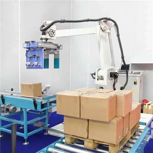
- Function: When executing tasks as a dedicated carton box robotic palletizer, the tool relies on a combination of lateral clamping force and positive mechanical support from below. Even if a box exhibits severe lateral bulge or weakened structural integrity, the bottom ledge physically supports the weight, preventing the package from slipping out during fast axis-4 and axis-6 rotations.
Independent Check-Valve Vacuum System (Bellows Style Suction Cups)
- Design Configuration: Multi-convolution silicone bellows cups are paired with individual multi-stage Venturi vacuum cartridges or independent ball-check flow valves.
- Function: The flexible bellows design allow individual suction cups to expand or compress independently up to 25mm to conform to warped, sloped, or uneven box top surfaces. If a specific cup encounters an uncorrectable gap and fails to seal, its independent check valve automatically seals its air path, maintaining full system vacuum pressure across the remaining operational cups.
3.2 End-of-Arm Tooling (EOAT) Selection Matrix
| Packaging Characteristics | Recommended Tooling Configuration | Primary Structural Material | Maximum Weight Capacity |
| Warped Surfaces / Variable Heights | Bellows vacuum pads with independent check valves and Z-axis spring suspension. | Anodized Aluminum / Silicone Cups | Up to 45kg per individual pick cycle. |
| Severe Side Bulge / High Weight | Mechanical side-clamping fingers with bottom-support ledges and proportional force control. | Structural Carbon Steel / Polyurethane | Up to 120kg payload capacity. |
| Unpredictable Linear Footprints | Combination tool: Top vacuum matrix paired with self-centering pneumatic side-shifters. | Aerospace Grade Aluminum Alloy | Up to 65kg total package mass. |
| Fragile / Low ECT Cardboard | High-surface-area low-vacuum plates utilizing high-flow regenerative blowers. | Machined Delrin / Closed-Cell Foam | Up to 30kg soft-handling limit. |
Read More: 《What Is A Corrugating Machine Splicer? A Pragmatic Introduction For Box Plant Managers》

4. Sensor Integration and PLC Control Automation
When mechanical and tooling solutions are insufficient to handle extreme dimensional variances, real-time electronic sensor feedback and dynamic PLC control algorithms are required to adapt the system's movements.
Electronic and Software Control Methods
Time-of-Flight (ToF) Laser Distance Profilers
- Implementation: Laser distance sensors are mounted directly to the EOAT frame or suspended above the incoming conveyor pick station.
- Logic: The sensor measures the precise distance to the package top surface before the pick cycle begins. The PLC processes this data to dynamically offset the Z-axis target coordinate, preventing collisions with over-filled or exceptionally tall packages.
Torque Limit Control and Active Servo Current Monitoring
- Implementation: The robot controller continuously monitors the electrical current draw of all axis servo motors via closed-loop feedback loops.
- Logic: If the gripper encounters an unexpected physical obstruction caused by a deformed or misplaced package, the servo current rises abnormally. The controller instantly detects this torque spike, halts axis motion within milliseconds, and triggers a safe recovery sequence to prevent component damage.
PLC Matrix-Shifting and Dynamic Coordinate Adjustment
- Implementation: A high-speed industrial PLC (e.g., Siemens S7-1500 or Beckhoff TwinCAT) connected via an EtherCAT or Profinet fieldbus network handles the system logic.
- Logic: The system measures the physical dimensions of incoming units in real time. If the package length varies from nominal values, the PLC software automatically shifts the placement coordinates (X and Y offsets) for the current layer, preventing spacing gaps or pallet overhang.
Read More: 《Paper Splicer ROI 2026: The Hard Financial Math Behind Automatic Roll Changes》
5. Supplier Sourcing Standards and Technical After-Sales Support
Managing package dimensional variance effectively requires investing in robust, field-proven hardware and well-engineered control software. Low-cost machinery often lacks the structural rigidity and software adaptability needed to process non-standard packaging materials without frequent system stoppages.
5.1 Technical Selection Criteria for Equipment Procurement
Structural Steel Thickness and Framework Mass
- Requirement: The main support gantry and robot base pedestals must be fabricated from heavy structural carbon steel (minimum Q235B or Q355B grade) with a wall thickness of no less than 8mm to 12mm.
- Reasoning: High structural mass effectively dampens the torsional forces and violent vibrations generated when heavy, irregularly shaped packages cause sudden shift adjustments during high-speed movements.
Open-Architecture PLC Software Frameworks
- Requirement: Avoid proprietary, locked control software. The equipment manufacturer must supply fully accessible, well-documented PLC ladder logic or structured text source code.
- Reasoning: Open access allows factory automation engineers to adjust tolerance limits, fine-tune settling delays, and integrate new sensor technologies as packaging material quality varies over time.
Stringent Factory Acceptance Testing (FAT) Protocols
- Requirement: Procurement contracts should require the machinery manufacturer to perform a comprehensive Factory Acceptance Test (FAT) utilizing defective material samples.
- Reasoning: The system must demonstrate its ability to process a continuous run of hundreds of intentionally warped, out-of-spec, and over-filled product samples at maximum speed without triggering safety faults or drop errors before the equipment is approved for shipment.
5.2 Mandatory Procurement Checklist for System Buyers
- Verify the equipment utilizes standard, globally available industrial components (e.g., Siemens, Allen-Bradley, SMC, SEW-Eurodrive) to ensure rapid local parts sourcing.
- Confirm the inclusion of remote diagnostic hardware modules (such as encrypted VPN routers) to allow factory engineers to perform off-site troubleshooting.
- Require documentation confirming the End-of-Arm Tooling (EOAT) has undergone finite element analysis (FEA) to verify structural integrity under maximum payload and offset torque conditions.
- Specify that the machine operator interface (HMI) must feature step-by-step graphical troubleshooting guides for quick fault resolution.
To discover how our heavy-duty industrial systems handle complex material variances, improve dry-end efficiency, and integrate with your existing production lines, explore our comprehensive equipment portfolio on our dedicated Robotic Palletizer category page. Partnering with an experienced automatic robotic palletizer manufacturer ensures your automated packaging lines maintain maximum uptime, even when processing challenging, out-of-spec packaging materials.
Read More: 《Running Low-GSM Recycled Medium: Fine-Tuning Splicer Tension Dynamics To Prevent Web Tears》