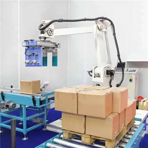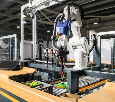
Executive Summary: Ensuring operational safety in automated packaging plants requires a rigorous, multi-layered approach to hazard control. Implementing an industrial palletizing robot or cobot system demands strict compliance with global standards, including ISO 12100, ISO 10218-1/2, ISO/TS 15066, and ISO 13849-1. A complete safeguarding architecture combines physical interlocked perimeter fencing, optical sensing technologies like safety light curtains and laser scanners, and advanced Safety PLC control logic. By correctly implementing risk assessments, calculating safety distances, and configuring smart muting and blanking functions, packaging facilities can maintain high line throughput while achieving zero-harm working environments and full CE and OSHA compliance.
1. Risk Assessment Framework: The Foundation of Cell Safety
Before installing a robotic palletizer, engineering teams must conduct a thorough risk assessment in accordance with ISO 12100, which governs safety of machinery through general principles for design, risk assessment, and risk reduction. Risk assessment is an iterative process applied throughout design, integration, and commissioning.
Key Risk Assessment Steps
- Hazard Identification: Identifying potential mechanical, electrical, and operational hazards across all operating modes, including automatic operation, manual teaching, maintenance, and jam clearing.
- Risk Estimation: Evaluating the severity of potential injury, the frequency or duration of exposure, and the probability of avoiding harm.
- Risk Reduction (The Three-Step Method): Applying inherently safe design measures to eliminate sharp edges or limit robot speed, integrating safeguarding measures like physical fences and light curtains, and providing clear warning signs and operator training protocols.
Global Standards Overview
ISO 12100: Focuses on general risk assessment methodology and risk reduction principles for machinery, evaluated through a risk estimation matrix.
ISO 10218-1/2: Sets mandatory safety requirements and cell design criteria for industrial robots, robot systems, and integration.
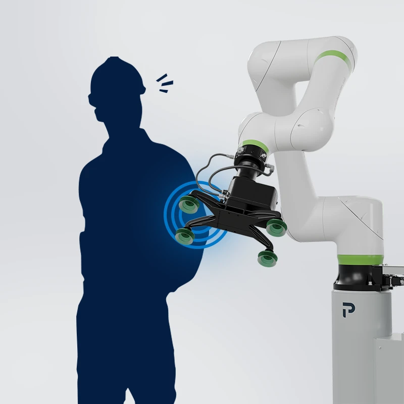
ISO/TS 15066: Provides specific guidance for collaborative robot operation and power and force limiting based on biomechanical pressure thresholds.
ISO 13849-1: Outlines safety-related parts of control systems design and validation, defining Performance Levels such as PLd or PLe.
IEC 62061: Regulates the functional safety of electrical and electronic safety-related control systems for machinery, defined by Safety Integrity Levels SIL2 or SIL3.
2. Physical Perimeter Fencing and Guarding Architecture
Physical perimeter fencing provides the primary hard barrier preventing unauthorized human entry into the hazardous movement envelope of an industrial palletizing robot arm.
Perimeter Fence Design Requirements
- Minimum Height Regulations: In compliance with ISO 13857, hard guarding fences must stand at a minimum height of 2,000 millimeters above the floor to prevent operators from reaching over into the hazard zone.
- Ground Clearance: The bottom mesh frame must maintain a ground clearance of 150 to 200 millimeters to prevent personnel from crawling under while allowing easy washdown and floor cleaning.
- Mesh Aperture Size: Mesh openings must prevent fingers or hands from reaching structural hazards. Standard 50 by 50 millimeter wire mesh requires a minimum safety distance of 200 millimeters from any moving mechanical component.
Cell Access and Interlock Sequence
During standard operation, the robot cell is fully locked. When an operator requests entry via the HMI console, the control system initiates a controlled speed deceleration. Once the system triggers a Safe Torque Off state and verifies zero motion, the trapped-key or solenoid interlock releases the access gate, allowing safe manual entry into the cell.
All access doors built into physical perimeter fences must be fitted with dual-channel safety interlock switches featuring guard locking. Solenoid-locking safety switches keep access doors locked until the robot has reached a complete standstill. Trapped-key interlock systems require operators to remove a physical safety key from the gate console before opening the door, and carrying this key into the cell prevents third parties from closing the door and restarting auto-mode while personnel are inside.
3. Optical Safeguarding: Light Curtains and Laser Scanners
When physical barriers would restrict pallet infeed or outfeed transport lines, optical presence-sensing devices provide active electro-sensitive protective equipment.
Safety Light Curtains (Type 4, PL e)
Safety light curtains project an array of infrared beams across access openings. Interruption of any beam sends an immediate stop signal to the Safety PLC. Finger protection uses a 14-millimeter resolution and is installed near hazardous pinch points like end-of-arm tooling grippers. Hand protection utilizes a 30-millimeter resolution as the standard configuration around conveyors. Body detection and access control grids use a 300 to 500 millimeter resolution multi-beam setup for perimeter entry protection.
Safety Laser Scanners (Area Protection)
Safety laser scanners use Time-of-Flight laser reflection to monitor 2D floor areas around a palletizing robot system. They allow dynamic zone switching. As an operator approaches the warning zone, the scanner triggers an audible alarm and signals the robot controller to slow down to a safe reduced speed. If the operator steps closer into the inner protection zone, the scanner executes an immediate category 0 or category 1 safe stop.
4. Calculating Safety Distance (ISO 13855 Compliance)
Placing a safety light curtain too close to an industrial palletizing robot arm creates a severe safety hazard, as an operator could reach the hazardous movement zone before the robot arm comes to a complete stop.
The minimum safety distance is calculated according to ISO 13855 using a standardized formula. The required distance equals the human approach speed multiplied by the total system stopping time, plus an additional penetration distance based on sensor resolution. The human approach speed is typically set to 1,600 millimeters per second for body access or 2,000 millimeters per second for hand movements. The total system stopping performance time combines the response times of the optical sensor, the Safety PLC logic processing, and the robot controller actuator stopping mechanism. The additional penetration distance accounts for how far a hand or body part can break through the light beams before detection occurs.
In a practical application scenario, if the human approach speed is 1,600 millimeters per second, the total combined system stopping response time is 0.35 seconds, and the penetration depth allowance for a body detection grid is 850 millimeters, the calculation multiplies 1,600 by 0.35 to yield 560 millimeters. Adding the 850 millimeter penetration allowance results in a required minimum safety distance of 1,410 millimeters. Therefore, the light curtain must be mounted at least 1,410 millimeters away from the nearest robot sweep hazard line.
5. Material Passage Strategies: Muting vs. Blanking Functions
Automated packaging lines must allow finished pallet stacks or empty pallets to pass through perimeter openings without triggering false emergency stops, while still detecting human entry.
The Muting Function (Temporal Bypass)
Muting is a temporal bypass method that temporarily disables the light curtain during material entry or exit using photo-eye logic. The system relies on cross-pattern (X-Muting) or parallel (L-Muting) photoelectric sensors to recognize the specific shape and speed of an outgoing pallet. The primary benefit of muting is allowing the uninterrupted transfer of full pallet loads out of the cell, but its main limitation is requiring a strict timing sequence to prevent a human from trailing closely behind the pallet.
The Blanking Function (Spatial Disablement)
Blanking is a spatial disablement method where specific beams of the light curtain are disabled where fixed objects pass through the optical field. Fixed blanking continuously ignores stationary structural supports or roller bed frames. Floating blanking ignores moving objects of a defined size while maintaining beam protection above and below the object. The key limitation of blanking is that effective sensor resolution drops, requiring recalculated minimum safety distances.
6. Functional Safety Control Systems: ISO 13849-1 (PLd vs. PLe)
Connecting safety devices to standard, non-safety PLCs is a severe compliance violation. Modern palletizing robot systems mandate functional safety control architectures certified under ISO 13849-1.
The required Performance Level is determined by evaluating the severity of injury, the frequency of exposure, and the possibility of avoiding harm. Due to high payloads ranging from 20 to over 300 kilograms and high arm movement speeds, robotic palletizing cells almost universally mandate PLd or PLe under Category 3 or Category 4 architectures.
In a Category 3 or Category 4 safety control structure, dual-channel input signals from light curtains, gate interlocks, and emergency stop buttons are fed directly into a Safety PLC or dedicated safety controller. The safety controller performs failsafe cross-monitoring and redundant logic processing. It then sends dual-channel output signals to safety actuators, such as dual main contactors or the robot controller's Safe Torque Off input.
Key Safety Functions in Robot Controllers
- Safe Torque Off (STO): Cuts power to the robot motors without shutting down the controller electronics, preventing unexpected mechanical restarts.
- Safe Operational Stop (SOS): Monitors robot joint encoders to ensure the arm remains completely stationary while retaining full motor holding torque.
- Safely-Limited Speed (SLS): Limits maximum Tool Center Point speed during teach mode or reduced-speed manual operations, typically to 250 millimeters per second or less.
7. Collaborative Robots vs. Heavy Industrial Cells
Choosing between a collaborative robot palletizer and a traditional high-speed industrial arm fundamentally changes the cell's safety requirements.
Collaborative Palletizer (Cobot)
- Primary Safety Mechanism: Power and Force Limiting (PFL) via joint torque sensors.
- Standards Focus: Governed primarily by ISO/TS 15066 and ISO 10218-1.
- Pinch Point and EOAT Safety: Uses soft-padded grippers and force-limiting stops.
- Operating Speed & Footprint: Restricted to low speeds under 1.0 meter per second during collaborative mode, offering an ultra-compact footprint that often requires minimal or no guarding.
- Payload Capacity: Typically ranges from 8 to 25 kilograms.
Industrial Robotic Cell
- Primary Safety Mechanism: Physical interlocked perimeter fences and active light curtains.
- Standards Focus: Governed by ISO 10218-1/2 and ISO 13849-1.
- Pinch Point and EOAT Safety: Employs mechanical guarded grippers with high clamping force.
- Operating Speed & Footprint: Operates at unrestricted full speeds over 2.5 meters per second, requiring a large footprint for the full fenced envelope.
- Payload Capacity: Ranges from 50 kilograms to over 800 kilograms.
A cobot is only as safe as its tooling and payload. If a cobot holds a sharp-edged corrugated tray or heavy wood pallet, an exposed impact can still cause severe trauma. A full ISO 12100 risk assessment remains mandatory even for fence-less cobot cells.
8. On-Site Safety Troubleshooting Matrix for Plant Engineers
Even with certified safety hardware, improper installation or sensor misalignments lead to cell trips and unwanted downtime.
Common Safety System Diagnostics
- Intermittent Light Curtain Tripping: Often caused by vibration from nearby conveyors causing optical alignment shifts. To resolve this, reinforce mounting posts with anti-vibration dampening plates and re-align the optical axis using laser tools.
- Muting Fault During Pallet Exit: Occurs when muting sensors are activated out of sequence or due to irregular pallet shapes. Fix this by cleaning photoelectric lens faces and recalibrating X-muting sensor crossing angles and PLC timer windows.
- Safety PLC Cross-Circuit Faults: Indicates a short circuit between dual-channel safety input channels. Inspect field wiring terminal blocks for pinched wires and replace damaged cable runs with shielded twisted-pair cables.
- Robot Refuses Auto-Start After Gate Close: Typically happens because the safety controller requires a manual reset before restarting auto-mode logic. Confirm that the operator executed the manual reset button sequence from outside the cell and verify guard-locking solenoid status on the HMI.
- Laser Scanner False Stops from Dust: Caused by dust accumulation on optical lens windows triggering distance thresholds. Wipe scanner windows using anti-static wipes and adjust scanner contour field tolerances in software.
9. Safety Audit and Commissioning Checklist (FAT/SAT)
Before handing over an automated palletizing cell to production staff, safety engineers must complete and sign off on a functional safety validation checklist:
- E-Stop Circuit Testing: Press every Emergency Stop button on the HMI, teach pendant, and fence posts individually to confirm an immediate Safe Torque Off response.
- Safety Interlock Functionality: Verify that opening any physical fence gate immediately halts robot movement and prevents gate unlatching during operation.
- Light Curtain Stop Distance Verification: Perform physical intrusion tests using a stop-time measuring device to verify that the physical distance meets or exceeds the calculated ISO 13855 minimum.
- Muting Logic Failure Testing: Intentionally break light curtain beams out of the proper muting sequence to confirm the system triggers a hard safety stop.
- Manual Reset Location Check: Ensure all manual safety reset buttons are located strictly outside the hazardous enclosure, with a full, unobstructed view of the entire cell interior.
- Signage and Visual Warning Inspection: Verify that high-voltage labels, robot movement warning signs, and visual status beacons are clearly visible and fully functional.
10. Summary Protocol for Plant Managers
Building a fully compliant, high-output industrial palletizing robot cell requires balancing operational efficiency with strict risk mitigation.
First, conduct an ISO 12100 Risk Assessment early during the engineering layout phase to avoid costly late-stage cell redesigns. Second, combine hard physical perimeter guarding with certified Type 4 safety light curtains and safety laser scanners to secure entry and exit points. Third, always calculate minimum safety distances according to ISO 13855 to ensure stopping performance matches human approach speeds. Finally, implement Category 3 or 4 PLd/PLe dual-channel safety control architectures via dedicated Safety PLCs.
By establishing a robust, multi-layered safety architecture, packaging facilities can protect personnel, pass regulatory compliance audits without delay, and achieve uninterrupted long-term production.