In modern corrugated box manufacturing, plant layout and intralogistics design represent hidden drivers of bottom-line profitability. Many packaging converters invest heavily in high-speed corrugators and multi-color flexo folder gluers, only to discover that improper material flow, overcrowded work-in-process (WIP) zones, and excessive forklift handling drag down Overall Equipment Effectiveness (OEE) by 15% to 25%.
A strategically engineered factory layout minimizes material travel distances, eliminates bottlenecking between wet-end and dry-end processing, prevents sheet edge damage, and lowers operational labor costs. This guide provides a technical framework for optimizing floor space allocation, calculating WIP buffer zones, and deploying automated material handling systems across modern corrugated plants.

1. Fundamental Principles of Corrugated Plant Layout Design
Designing a high-yield corrugated plant requires establishing a continuous, unidirectional workflow that eliminates backtracking, cross-traffic collisions, and environmental contamination.
A. Unidirectional Flow Patterns
- Straight-Line Layout: Raw paper rolls enter at one end of the facility, move linearly through the corrugator, pass straight into the WIP curing buffer, enter converting machinery, and exit directly into the finished goods warehouse. This layout is ideal for narrow, elongated industrial plots.
- U-Shape / L-Shape Layout: Raw roll receiving and finished goods shipping share the same building facade or dock complex. This design centralizes loading dock infrastructure, optimizes forklift utilization, and minimizes outdoor yard traffic.
- The Zero-Cross Traffic Rule: Raw roll transport routes must never intersect with board-stack transport paths. Separating primary raw material corridors from converted board flows prevents forklift congestion and reduces workplace safety risks.
B. Environmental and Micro-Climate Zoning
- Wet-End Isolation: Corrugator single facers generate substantial steam heat, humidity, and ambient paper dust. The wet end must be physically segregated or ventilated away from humidity-sensitive flexo printing stations and electronic control rooms.
- Curing Zone Environment: Newly corrugated board requires 4 to 12 hours of controlled conditioning to stabilize moisture and release internal sheet stress. The curing zone requires uniform airflow and temperature control to prevent severe board warping (up-warp, down-warp, or S-warp) before converting.
C. Modular Functional Zoning Architecture
- RAW (Paper Roll Storage): Positioned immediately adjacent to the corrugator mill roll stands, with dedicated turning clearance for clamp trucks.
- COR (Corrugator Production Line): Main linear equipment footprint, incorporating maintenance access perimeters and cassette-roll clearance zones.
- WIP (Work-in-Process Buffer): The operational surge tank connecting primary board manufacturing with downstream converting equipment.
- CON (Converting & Finishing): Flexo folder gluers, rotary die-cutters, printer slotters, and automated bundling lines.
- FG (Finished Goods Warehouse): Storage staging directly adjacent to strapping stations and shipping docks.
2. Floor Space Allocation and WIP Buffer Calculations
Miscalculating Work-in-Process (WIP) storage is one of the most common factory design flaws. An undersized WIP zone starves downstream converting equipment during order changes, while an oversized WIP zone consumes valuable real estate and encourages excessive inventory holding.
Paper Roll Yard Space Planning
Raw paper roll storage requires high structural floor load ratings (typically 3 to 5 metric tons/m²). Implementing vertical roll stacking increases floor space utilization by up to 40% compared to horizontal staging. Main transport aisles for paper roll clamp trucks require a minimum clear width of 4.0 to 4.5 meters to ensure safe, continuous operation.
Scientific WIP Buffer Sizing Formula
To accurately dimension the required WIP floor space, plant engineers must factor in peak corrugator output, required curing times, average stack height, and aisle utilization factors:
- Peak Daily Output: The maximum linear output generated by the corrugator line over a 24-hour period.
- Average Curing Time: Standard conditioning window (typically 6 to 8 hours for double-wall, 4 to 6 hours for single-wall board).
- Floor Utilization Factor: The usable storage ratio after deducting main shuttle car tracks and secondary pedestrian aisles (typically 0.60 to 0.65).
- Industry Benchmark: In a modern packaging plant, the WIP buffer zone typically accounts for 25% to 35% of total plant floor space.

3. Material Handling & Intralogistics Automation
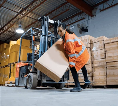
Traditional manual forklift transport of corrugated stacks introduces severe edge damage, causing up to 3% sheet scrap before board even reaches the converting stage. Modern plants deploy automated intralogistics systems to transport board seamlessly across zones.
A. Plastic Modular Belt Conveyors
Replacing legacy steel roller conveyors with plastic modular belt systems eliminates point-contact pressure on corrugated stacks. The continuous, flat surface of plastic modular belts supports the bottom liner evenly, preventing bottom-sheet scoring, fluting crushing, and edge fraying.
B. Automated Transfer Cars (Shuttle Cars)
Motorized transfer cars operating on flush ground rails serve as the primary link between the corrugator downstacker, the WIP curing lanes, and individual flexo printer feeders. Controlled via central Manufacturing Execution Systems (MES), automated shuttle cars dispatch specific board lots directly to designated printing lines without manual operator intervention.
C. AGVs and AMRs for Paper Rolls and Finished Goods
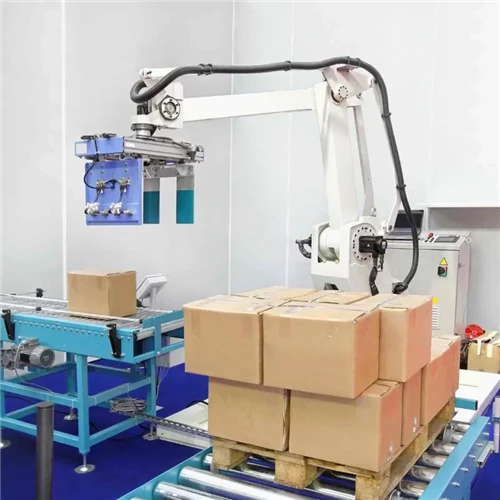
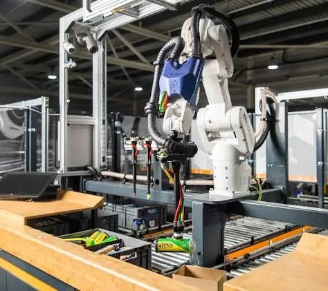
Autonomous Guided Vehicles (AGVs) fitted with heavy-duty paper clamps are replacing manual clamp trucks for raw roll delivery to the corrugator wet end. Similarly, Autonomous Mobile Robots (AMRs) manage finished palletized goods transport from strapping stations to warehouse staging lanes.
4. Factory Layout Parameter Reference Matrix
The table below provides dimensional, throughput, and intralogistics benchmarks across different factory production scales:
| Planning Parameter | Small Box Converter | Medium Integrated Plant | Large High-Speed Packaging Hub |
|---|---|---|---|
| Target Floor Space | 5,000 – 10,000 m² | 15,000 – 30,000 m² | 40,000+ m² |
| Corrugator Line Speed | 120 – 150 m/min | 180 – 220 m/min | 280 – 350 m/min |
| WIP Buffer Capacity | 4 – 6 Hours Buffer | 8 – 12 Hours Buffer | 12 – 16 Hours Automated High-Bay Buffer |
| Material Handling System | Manual Forklift + Ground Rollers | Auto Shuttle Cars + Forklifts | Fully Automated Modular Belts + AGVs/AMRs |
| Board Handling Scrap Target | < 3.0% Edge Scrap | < 1.5% Edge Scrap | < 0.5% Edge Scrap |
| Staffing per 10,000 m² | 20 – 30 Operators | 10 – 15 Operators | < 8 Operators |
5. Financial Impact and ROI of Layout Optimization
Optimizing plant layout and intralogistics delivers measurable financial returns through material scrap reduction, labor optimization, and increased converting machine uptime.
Key Financial ROI Metrics:
- Material Scrap Reduction: Transitioning from manual forklift stack handling to automated plastic modular conveyor lines reduces sheet edge damage from 3.0% to under 0.5%. For a facility processing $10,000,000 in paperboard annually, this saves up to $250,000 in raw material waste per year.
- Converting Machine OEE Gains: Eliminating material starvation at flexo printing lines through automated WIP shuttle cars increases downstream converting uptime by 10% to 18%.
- Labor Cost Efficiency: Automated intralogistics cuts internal transport headcount by up to 60%, allowing plants to reallocate personnel to high-value quality and operational tasks.

6. Step-by-Step Implementation Roadmap
Corrugated packaging plants planning a layout redesign or greenfield build should follow a structured four-phase workflow:
- Phase 1: Capacity and Product Mix Modeling: Define 5-year growth targets, target board wall ratios (3-ply, 5-ply, 7-ply), and peak daily tonnage requirements.
- Phase 2: Value Stream Mapping (VSM): Audit existing or projected material travel lines. Identify bottlenecks, transport intersections, and manual touchpoints.
- Phase 3: WIP and Intralogistics Engineering: Calculate precise WIP buffer dimensions and select appropriate conveyor technology (modular plastic belts, ground transfer cars, or AGV loops).
- Phase 4: MES/WMS System Integration: Link material handling control systems with central Manufacturing Execution Systems (MES) to automate order tracking, stack routing, and warehouse staging.
7. Strategic Conclusion
A well-engineered corrugated factory layout transforms floor space into a lean, continuous production machine. By establishing unidirectional workflows, accurately dimensioning WIP curing buffers, and replacing manual stack handling with automated modular belt conveyors and transfer cars, corrugated packaging manufacturers achieve maximum throughput, minimal scrap rates, and long-term operational profitability.
If you need design services for a corrugated cardboard box manufacturing plant, please contact our engineers for a free quote.