Flexibility in layout design allows modern packaging operations to install high-throughput palletizing robot systems inside compact, multi-level, or irregularly shaped factory footprints without knocking down walls or undergoing costly civil reconstruction. By combining modular articulated arms, heavy-duty shuttle transfer cars, and integrated vertical lifters, box plants can automate downstream end-of-line stacking even when the primary palletizing cell is isolated from the warehouse or situated near outdoor staging yards.
Core Layout Configurations For Space-Constrained Box Plants
| Layout Configuration | Core Equipment Components | Primary Footprint Advantage | Ideal Plant Application |
| Inline Compact Cell | Articulated arm, integrated safety scanners, dual pallet docks | Fits within 3.5m x 3.5m footprint | Small plants with direct line-of-sight to warehousing |
| Cross-Wall Transfer Line | Stacking arm, motor-driven shuttle car, weatherproof wall-hatch | Isolates indoor production from outdoor loading | Plants with outdoor pallet storage or dusty environments |
| Vertical Elevator Link | Low-level palletizer, hydraulic lifter, interlocked safety gates | Utilizes vertical air space instead of floor area | Multi-story factories or mezzanine loading docks |
| Distributed Multi-Line Hub | Shuttle conveyor network, centralized high-speed arm, multi-docking station | Consolidates output from multiple converting lines into one cell | High-volume facilities with narrow access aisles |
Overcoming Tight Floor Plans: Architectural Challenges in End-of-Line Packaging
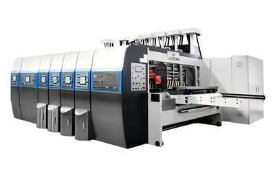
Corrugated box converting lines-such as Flexo Folder Gluers (FFGs) and Rotary Die Cutters (RDCs)-generate finished bundles at high linear speeds. Traditionally, downstream automation required expansive concrete pads to accommodate massive mechanical gantries, long gravity rollers, and wide perimeter safety fencing. For legacy box plants built decades ago, floor space remains the single greatest bottleneck to modernizing operations.
Plant managers routinely face three structural roadblocks when evaluating automation:
- Inflexible Pillar Layouts: Support columns placed at short intervals prevent straight-line conveyor runs to the warehouse.
- Pinched Transit Corridors: Forklifts cannot maneuver safely near the outfeed of high-speed converting machinery due to narrow driving aisles.
- Unusable Outdoor Real Estate: Secondary staging space exists outside the physical factory walls, but extreme weather and temperature swings make placing sensitive electronics outdoors risky.
Deploying a modular industrial palletizing robot solves these spatial limitations by separating the bundle-receiving phase from the final pallet-discharge phase. Rather than forcing a rigid, linear flow from folder gluer to forklift truck, modern articulated robotic cells allow engineering teams to redirect corrugated bundles around structural columns, through narrow wall openings, or up to elevated mezzanines.
Practical Application Case Study: Retrofitting a Chilean Box Plant Under Strict Layout Constraints
To understand how flexible material handling components solve floor-space limits, consider an installation engineered for a mid-sized corrugated packaging supplier located in Santiago, Chile.
The Operational Bottleneck
The client operated a high-speed flexo converting line inside an urban facility with severe structural boundaries. Their converting machine produced up to 10,000 corrugated boxes per hour. However, the physical distance between the folder gluer outfeed and the factory's structural boundary wall was precisely 4.2 meters. Behind this exterior wall lay an open-air, covered loading courtyard used for staging finished loads onto flatbed trucks.
Traditional end-of-line machinery vendors quoted layout proposals requiring a minimum clearance of 8 meters, which would have forced the client to demolish structural support pillars or shrink their primary box-making line length. The plant relied on six workers per shift manually lifting and stacking heavy corrugated bundles. This manual vs robot palletize dynamic created severe production delays, high worker fatigue during peak summer months, and frequent bundle drops that ruined outer linerboards.
The Engineering Solution
Instead of altering the building's infrastructure, an integrated system was engineered utilizing three core components:
- A High-Density Articulated Arm: A compact 4-axis palletizing robot arm featuring a 3.1-meter reach was anchored within the 4.2-meter indoor zone. A multi-zone vacuum suction gripper was fitted to handle both single corrugated bundles and full top-cap sheets.
- Automated Cross-Wall Shuttle Car: A motor-driven transfer cart running on embedded floor rails was positioned directly below the robot's palletization zone.
- Pneumatic Wall-Hatch Interlock: A heavy-duty, insulated weather door was cut into the industrial wall, wired directly into the main Programmable Logic Controller (PLC) system.
System Execution & Operational Flow
Under the redesigned workflow, incoming corrugated bundles travel off the converting line directly into the compact indoor cell. The case palletizer arm picks incoming bundles and builds structured, interlocked pallet loads on top of the waiting shuttle car inside the indoor zone.
Once a load reaches its full stack height, the system executes an automated sequence:
- The main PLC verifies that the outdoor staging track is clear using photoelectric optical sensors.
- The pneumatic wall-hatch door lifts vertically.
- The heavy-duty motorized shuttle car travels horizontally along the floor track, moving the completed 1,200 kg pallet out through the wall hatch into the outdoor courtyard.
- The outdoor forklift operator retrieves the pallet load directly from the shuttle rails without ever entering the indoor production floor.
- The shuttle car returns inside, the weather door closes, and the cycle repeats without interrupting the converting line.
Measured Financial & Operational Results
By implementing this space-adapted engineering design, the Santiago plant achieved immediate operational improvements:
- Zero Floor-Space Expansion Costs: The factory avoided an estimated $180,000 USD in structural extension costs.
- Labor Reallocation: Six manual stackers were retrained as machine operators and quality control technicians across other plant sections.
- Throughput Increase: Output increased by 32% because the converting line no longer ran at reduced speeds to accommodate manual lifting limits.
- Rapid Capital Recovery: Considering total equipment procurement, freight, and commissioning expenses, the calculated payback period was achieved in under 14 months.
Key Equipment Components For Adapting To Complex Footprints
Achieving layout flexibility requires combining specialized end-of-line hardware modules. Rather than treating the cell as a static piece of machinery, packaging engineers treat these components as building blocks.
Heavy-Duty Shuttle Transfer Cars (Flatbed Rail Transporters)
Shuttle cars act as the horizontal bridge between isolated factory zones. Mounted on low-profile steel rails embedded flush with the concrete floor, these motorized platforms move loaded pallets along specified paths.
- Linear Travel Distances: From 3 meters to over 50 meters across factory floors.
- Drive Systems: Variable Frequency Drive (VFD) electric motors coupled with rack-and-pinion or heavy-duty chain drives for smooth acceleration and deceleration, preventing stack collapse.
- Safety Integration: Integrated 2D laser bumpers automatically stop movement if a worker, hand truck, or debris enters the rail path.
Vertical Elevator Systems & Hydraulic Lifts
When horizontal floor space is exhausted, vertical space provides an efficient alternative. Integrated vertical lifters transport individual bundles or complete built loads between elevated floor levels.
- Lower-to-Upper Floor Transfers: Transport finished corrugated loads built on a ground-level floor up to a secondary floor or elevated loading dock.
- Overhead Conveying Corridors: Elevate finished bundles 4 meters above the factory floor, conveying them above main transit aisles and dropping them directly into a remote case palletizer workstation.
Modular Shuttle Infeed Conveyors
To feed corrugated bundles into tight spaces, modular zero-pressure accumulation conveyors can turn 90-degree or 180-degree corners in extremely tight radii.
- Right-Angle Pop-Up Transfers: Use pneumatic belts or chain lifters to redirect bundle traffic without needing long, sweeping curved conveyors.
- Incline Slat Conveyors: Elevate incoming bundles gradually over other production equipment to maximize floor space usage.
Financial Metrics: Evaluating ROI And Procurement Factors
Selecting end-of-line equipment requires analyzing capital expenditures against long-term operational savings. Sourcing machinery directly from an overseas supplier like a palletizing robot China manufacturer offers significant initial capital advantages, provided plant managers evaluate total life-cycle costs.
Total Cost of Ownership (TCO) Breakdown
A comprehensive capital assessment goes beyond the initial machinery purchase price tag. Plant engineers should balance hardware costs against installation, maintenance, and utility requirements.
- Robotic Arm & EOAT Gripper Assembly
- Shuttle Cars, Track Rails & Vertical Elevators
- Safety Fencing, Light Curtains & Interlocks
- Shipping, Import Duties & Engineering Design Fees
- Electricity & Compressed Air Consumption
- Preventative Maintenance (Grease, Belts, Sensors)
- Operator Training & Spare Parts Inventory
- Initial Equipment Purchase: Comparing overseas manufacturing costs with domestic alternatives often reveals a 30% to 50% savings on structural mechanical components, shuttle rails, and conveyor beds.
- Custom Layout Engineering Fees: Factor in custom CAD layout designs and PLC programming adjustments needed to handle non-standard shuttle movements or wall-hatch timing.
- Utility Consumption: Electric servo-driven arms consume drastically less energy than pneumatic-heavy conventional machines, lowering monthly power bills.
Capital Expenditure Comparison
The table below outlines approximate cost ranges and metrics for automating a single high-speed corrugated converting line based on configuration complexity.
| System Parameter | Basic Standalone Cell | Modular Shuttle-Linked Cell | Multi-Story Integrated System |
| Typical Equipment Capital Range | $45,000 – $70,000 USD | $75,000 – $120,000 USD | $130,000 – $195,000 USD |
| Average Installation Footprint | 16 m² | 25 m² (Split zones) | 35 m² (Multi-level) |
| Footprint Modification Costs | Low | Very Low (Uses existing space) | Moderate (Floor penetrations) |
| Estimated Payback Period | 8 – 12 Months | 11 – 16 Months | 14 – 22 Months |
| Throughput Capacity | Up to 12 bundles/min | Up to 18 bundles/min | Up to 22 bundles/min |
When requesting a palletizing robot price estimate from equipment vendors, plant managers must ensure quotes include all secondary components-such as safety light curtains, shuttle rail floor anchors, End-of-Arm Tooling (EOAT), and remote PLC communication modules.
Mechanical Gripper Design For Variable Corrugated Bundles
Handling corrugated paper bundles requires tailored End-of-Arm Tooling (EOAT). Unlike rigid plastic crates or rigid wooden boxes, corrugated sheets, die-cut blanks, and folded cartons present variable surfaces, air permeability, and loose strapping.
Vacuum Sponge Matrix Grippers
Vacuum-based EOAT configurations use high-flow, low-vacuum pumps paired with soft foam sponge pads rather than traditional rubber suction cups.
- Surface Adaptation: The foam conforms across uneven surfaces, open top flaps, and bundle strapping channels without losing seal integrity.
- Porosity Compensation: High-volume vacuum blowers overcome high paper porosity in low-GSM recycled corrugated liners.
Mechanical Bottom-Support Forks
For unstrapped bundles or heavy die-cut sheets prone to slipping, mechanical bottom-support fingers slide beneath the corrugated load before lifting.
- Zero Surface Damage: Eliminates top-liner tear marks caused by intense vacuum pressure on thin fluting (such as E-flute or F-flute micro-corrugated board).
- High Payload Security: Provides reliable physical support during fast, high-acceleration robot arm swings across wide travel radii.
Step-By-Step Engineering Guide: Designing Your Space-Adapted Layout
If your factory operates within tight physical confines, follow this step-by-step layout design workflow to evaluate feasibility before requesting equipment proposals.
Step 1: Establish Precise Architectural Parameters
Map out the physical boundaries of your downstream area using 3D laser scanners or high-accuracy distance measuring tools:
- Measure exact clearance heights under overhead water pipes, electrical trays, and roof trusses.
- Locate every structural concrete pillar within 15 meters of your converting line outfeed.
- Mark primary truck transit corridors and ensure a minimum 2.5-meter clearance for forklift traffic.
Step 2: Calculate Peak Line Speeds and Payload Limits
Determine the maximum mechanical output of your upstream converting machinery:
- Calculate peak bundle production rates (e.g., 20 bundles per minute).
- Calculate maximum bundle weight and maximum target stack height (including pallet height).
- Select a palletizing robot arms model with a payload rating that covers both the heaviest bundle weight and the total weight of the EOAT gripper assembly combined.
Step 3: Determine Horizontal & Vertical Transit Routes
Identify underutilized factory areas that can serve as secondary staging or transit zones:
- Evaluate exterior walls where a motorized shuttle car could transport completed pallets outdoors or into an adjacent bay.
- Check if overhead vertical space allows for an elevated bundle conveyor bridge.
- Assess whether an automated elevator can transfer completed stacks to a secondary floor level or loading dock.
Step 4: Configure Safety Boundaries & Sensor Interlocks
Space-saving automation requires tight integration of safety devices to comply with international industrial safety codes (ISO 10218-2 / ANSI/RIA R15.06):
- Replace physical mesh perimeter fencing with dual-zone safety laser scanners where foot traffic is light.
- Install safety light curtains with built-in muting functions at pallet discharge ports to allow automated shuttle transit while stopping human entry.
- Integrate hardware-level emergency stop interlocks between the main converting line, the central PLC, shuttle car drives, and automatic doors.
FAQ
1,Can a palletizing robot system operate effectively in unheated or outdoor environments?
Yes. While the articulated arm and delicate PLC control cabinets should remain inside a temperature-controlled or covered environment, the discharge staging area can reside outdoors. Using motorized shuttle cars running through pneumatic weather doors allows the pallet stack to be moved outdoors into covered loading yards immediately upon completion.
2,What maintenance is required for shuttle transfer tracks embedded in factory floors?
Shuttle tracks require simple, routine upkeep: keeping the rail grooves clean of corrugated dust, paper scraps, and strapping debris using compressed air or industrial vacuuming. Drive chains and rack-and-pinion assemblies should be inspected and lubricated monthly.
3,How do systems adjust when box dimensions change frequently?
Modern systems use smart recipe-management software within the HMI (Human-Machine Interface). When changing production runs on the flexo folder gluer, the operator selects the new box dimensions and layer pattern from a touchscreen menu. The control system automatically calculates revised picking positions, shuttle indexing stops, and stack height limits in seconds without manual tool adjustments.
To evaluate your facility's layout options, contact our engineering team today with your plant dimensions, converting line specs, and target throughput rates. Our technical team will generate a customized 2D/3D CAD layout drawing and a complete technical feasibility report for your facility.